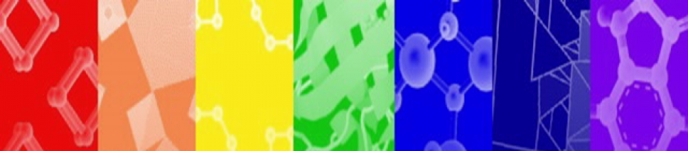
What does it look like:

The image shows a computer simulation of tetrahedral amorphous carbon grown on a substrate (at the right). The red atoms are diamond-like, the blue atoms are graphite-like and the green atoms. In this image the carbon atoms would have impacted the surface from the left hand side with an energy of 70eV (a velocity of about 85km/s-1). The green, blue and red atoms have two, three, and four neighbours respectively, where “neighbor” means “within 1.85A”.
What is it?
It’s another allotrope of carbon, this time tetrahedral amorphous carbon (ta-C). Tetrahedral amorphous carbon is not a natural material. It’s formed by firing carbon atoms at high speed onto a substrate using a plasma device such as a vacuum arc.
An amorphous material is one that has no long term regularly repeating structure: it can have local order- order that persists for a couple of unit cells- but no long range order. A good example of an amorphous material is window glass, which is mostly silicon dioxide (SiO2) with some other stuff thrown in.
Now it may be a bit of a stretch to include ta-C on a blog about crystals, given that “amorphous” means “it’s not a crystal”. However, if we define crystallography in the most general sense as “what gets talked about at crystallography conferences, even if it’s hidden away in the dingy corner of the venue”, then we can use that as an excuse to talk about a fascinating range of materials.
Amorphous carbon (aC) as a structure type is hardly new. It can be found in natural carbon materials such as coal and Rosalind Franklin did pioneering measurements on aC in the 1950’s.
Even though amorphous materials are disordered (by definition!) you can still say things about their bonding and structure. Naturally occurring aC tends to be graphitic in nature: most of the bonds in the material are graphite-like (planar) sp2 bonds, and each carbon is more or less surrounded by three other carbon atoms (like graphite).
In tetrahedral amorphous carbon, the majority of bonds are diamond-like (tetrahedral) sp3 bonds and the majority of the carbon atoms have four nearest neighbours (like diamond). Amorphous carbon can be characterized by the proportion of the two bond types.
In a crystal, we can characterise atomic distances to a certain degree of accuracy. In diamond, the distance between adjacent (“nearest-neighbour”) carbon atoms is 1.54A. This is true throughout the crystal.
In an amorphous material, there’s no longer a consistent, exact distance between atoms. Instead you have to ask the question, “for any given carbon atom, what is the probability I’ll find another carbon atom at a particular radius from that one?” This is called the radial distribution function (RDF). Let’s have a look at the following graph:
 The important thing here is the black dots which are experimental data (the other lines are various models). At 1.5A is a broad hump which says that, for any individual carbon, its nearest neighbor is about 1.5A, but really it could be anywhere between 1.3 and 1.7A or so. The next nearest neighbor is about 2.5A. In contrast, you won’t find any carbon atoms that are 2A apart from each other. Finally there are no atoms closer to each other than about 1.2A. Otherwise, that would be called “cold fusion”.
So while the ta-C structure is disordered, it’s not entirely random. Each individual atom looks “a bit diamond-y”, and this idea of “order within chaos” is one of the interesting aspects of amorphous materials.
One of the main progenitors of the current interest in ta-C was a seminal 1991 paper, which introduced the idea of producing thin films of the material using vacuum arc. A vacuum arc is a plasma source that produces a stream of energetic, high speed ions. It’s quite different to conventional plasma sources used to make thin films. So the question arose: “what happens if we whack these high speed ions into a surface?” and the answer is “if you do it with carbon, you get a new allotrope”.
The field blossomed, and in the way of so much physics that started as a “what-if” question, is leading to applications such as this one. One of the fascinating aspects of physics (and arguably science in general) is that it doesn’t neatly divide into “pure” and “applied” research. The field began as a “relatively” pure physics project, albeit in an Applied Physics department. A great deal of the follow up modeling (so essential to understanding What Is Going On) could be called “pure” research. You might like to make some sort of inference from this. I couldn’t possibly comment.
Where does the structure come from?
The images are from the 2005 paper by Nigel Marks published in Diamonds and Related Materials, a journal with a surprisingly large research area with many unresolved scientific questions. For example it has not been resolved whether or not Related Materials are also a girl’s best friend.
A good starting point for amorphous materials is the book “Powder Diffraction: Theory and Practice” edited by Dinnebier and Billinge, which has a nice chapter introducing RDFs, G(r) and all the rest.
A. Marks, “Thin film deposition of tetrahedral amorphous carbon: a molecular dynamics study”, Diamond & Related Materials 14 (2005) 1223–1231
D.R. McKenzie et. al., “Compressive-Stress-Induced Formation of Thin-Film Tetrahedral Amorphous Carbon,” Phys. Rev. Lett., 67 (1991) 773
Fanxin Liu et al., “Released Plasmonic Electric Field of Ultrathin Tetrahedral-Amorphous-Carbon Films Coated Ag Nanoparticles for SERS”, Scientific Reports 4, Article number: 4494, doi:10.1038/srep04494. This one’s open access.
Peter J.F. Harris, “Rosalind Franklin’s work on coal, carbon, and graphite”, Interdisciplinary Science Reviews, 26 (2001) 204